

Salinometer is an instrument for the determination of the salinity of seawater aboard a ship or in the laboratory by an electrical conductivity method.
The first apparatus of this kind was constructed by the U.S. National Bureau of Standards in 1930 and is known as the Wenner-Smith-Soule Salinity Bridge. NBS engineer Frank Wenner and U.S. Coast Guard Oceanographers Ed. Smith and F.Soule introduced them in 1934 into the oceanographic practice of the International Ice Patrol Vessels. Salinity Bridge directly measured the ratio of conductivity between the standard sample and water by using two measuring contact cells.
Before the apparatus can be used for the determination of the salinity of a number of samples of sea water, preliminary tests andadjustments must be made. These consist of putting into the Y cell a suitable sample of sea water and determining and recording thesetting of Q for each of the X cells to be used.
First, all the cells to be used should be filled with sea water of the same, though not necessarily known salinity. Then with any one of the cells used as a Y cell, any other cell used as an X cell, and Q set at about the center of its range, a setting of the index of the slide wire is found at which the bridge is balanced. It should be remembered that in any case a balance of the bridge involves a proper setting of the mutual inductance and of the contact on the Wagner branch. This setting of Q should be recorded; then another cell is used as an X cell and the bridge balanced this time without changing the setting of the slide wire index, but by a change in the setting of Q. In like manner, a setting of Q, which gives a balance of the bridge for each of the remaining cells used as X cells, is determined and recorded. This serves merely to find the differences in the cell constants and which one of the cells has the lowest resistance when all are filled with seawater of the same salinity.

In case no more cells are available than it is expected will be used at any one time, that cell whose resistance differs most from the average resistance of all may be selected for use as the Y cell, and of theremaining cells that one having the lowest resistance may be usedasan X cell in the selection of a sample of sea water of suitable salinityfor use in the Y cell.
This X cell is then filled with a sample of seawater of definitely known salinity.

The cells were maintained at the same temperature. Salinity was calculated from the ratio of conductivity. This instrument provided measurements at least as precise as those obtained by the method of Knudsen but it was simpler and faster to be used. The temperature has an important effect on the conductivity of seawater. An increase in the temperature of 0.01°C has the same effect on conductivity as an increase in practical salinity of 0.01. The electrical salinity bridge was the result of the oceanographic demands of the International Ice Patrol in the North Atlantic Ocean. An accurate and rugged instrument suited to severe sea conditions was developed, and instruments built and used with satisfactory results. The instrument as described compares well in performance with titration measurements, is capable of individual measurements accurate to within 0.02 %o, and is well adapted to the measurement of salinity. The temperature compensation has been tested and found to be effective and in agreement with the results expected from theory. The calibrations of actual instruments have been compared and can be fairly well predicted for similar instruments built in the future.
Currently, oceanographers need a practical salinity determination accuracy of ±0.003 or better in the deep ocean which brought the development of instruments with a higher degree of accuracy.

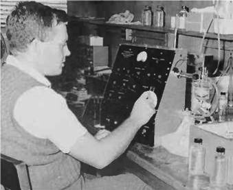
For example in 1956 Alvine Bradshaw and Karl Schleicher (Woods Hole Oceanographic Institution or WHOI), like in 1958 Roland Cox (National Institute of Oceanography, the U.K.), developed a laboratory salinometer made up of 2-electrodes conductivity cells in a bath of oil thermostat equipped with a heating, a refrigeration, an electronic control of temperature and a bridge of measurement of conductivity. Salinity was measured by comparing the conductivity of the taking away to be measured with that of standard seawater after balancing of the temperature of the two samples in the oil bath. These instruments were large, complex, heavy (more than 200 kg) and thus non-marketable. However, they reached the necessary precision of ± 0.003. The equipment consists of the bridge-oscillator detector unit, a refrigerated oil-tight constant-temperature bath, seven conductivity cells mounted in the bath, a refrigerator unit and controls, a proportional-type temperature controller, a constant-voltage supply for the electronic parts, and a suction system for emptying the cells.

The salinometer is calibrated in the laboratory by a lengthy series of measurements of Copenhagen water and other carefully prepared standard solutions whose salinities have been determined by repeated titrations. The final calibration may be expressed in graphic form at a large scale, or a salinity versus- resistance table may be computed. How often the calibration must be renewed is uncertain but should probably be done annually. When in use to measure salinities, one cell, called the reference cell, is filled with substandard seawater whose salinity has been determined by careful titration and the six measuring cells are filled with water from the samples. About 20 minutes are required to bring them to temperature equilibrium before measurement can begin.

One of the measuring cells is then balanced on the bridge with the reference cell, the resistance reading is recorded and the procedure repeated with each of the six cells. Each sample is measured twice but in different cells. Salinities are obtained from the graph or tables using the resistance reading as an entering argument. The reference cell and water are compared with a standard daily or more frequently if the salinity drift requires it. When properly used the results are far more accurate than titrations at sea, salinity determinations can be made more rapidly, and the equipment can be satisfactorily operated with less-skilled personnel.
In 1961 Bruce Hamon and Neil Brown, who worked with the division of fishing and the oceanography of the Commonwealth Science and Industrial Research Organization (CSIRO) in Australia, designed a portable salinometer of an approximate weight of 15 kilogrammes. He used a thermistor and a bridge of resistances to compensate for in a precise way the effect of the temperature on the report/ratio of conductivity what avoided the use of an oil bath thermostated. This apparatus whose precision was of ± 0.003, was manufactured in great quantity. It used a sensor with induction placed in a plexiglass container. The cell containing standard water in the preceding apparatus was replaced by a branch of the bridge of measurement which it was necessary to gauge before passing the samples. In the high part of the container, an agitator allowed to maintain a good mixture quickly.
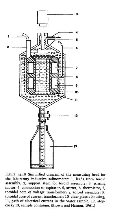
Water was in contact with two thermistors. A thermistor was placed in the compensating network of the effect of temperature, the other thermistor measured the temperature of the sample with a precision of ± 0.1°C what made it possible to calculate which would have been the ratio of conductivity if measurement had been carried out with 15°C (or 20°C). It is indeed for this temperature that the equation was established – said “equation of state of seawater” – which allows the calculation of salinity. The use of a sensor with induction in this salinometer eliminated the problems from drift existing with the cells with two electrodes. This drift is due to the impedance of polarization, identical to an electric resistance, which exists between each electrode and the seawater. The drift was reduced in an important way by using electrodes of turntable covered with passivated platinum. However, there remained a drift sufficiently important to frequently require a cleaning of the cells and a Re-calibration with standard seawater. The sensors of conductivity to induction consist of two superimposed toroidal transformers so that their central hole is aligned.

The sea water surrounds them completely and filled the central hole so that that forms a whorl common to both transformers. An alternating voltage is applied to the one of the transformers what induces an electrical current in the sea water circuit. This current is proportional to conductivity. It is measured by the second transformer. Although these cells are more stable than the cells with two electrodes electric resistance causes minor instabilities which must be compensated by frequent calibrations.
Inductively coupled conductivity sensors consist of two toroid-shaped transformers mounted close together with their center holes aligned one above the other. Seawater completely surrounds both transformers and fills the center holes so that the seawater forms a current common to both transformers. An alternating-current voltage applied to one transformer induces an electric current in the seawater circuit proportional to conductivity. The induced current is measured by the second transformer. Although these cells are more stable than two-electrode cells, the electrical resistance the windings causes minor instability that must be compensated for by frequent recalibration.
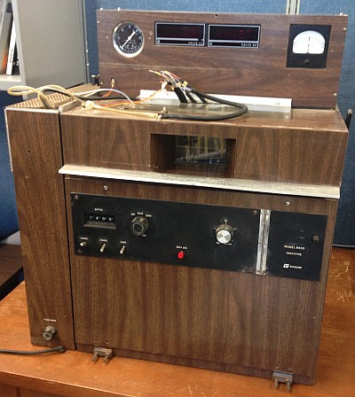
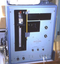
In 1975 Tim Dauphinee (National Research Council of Canada in Ottawa) designed a laboratory salinometer (commercially available as the AUTOSAL) that is still widely used by oceanographers today. AUTOSAL uses a contact four-electrode cell immersed in a well thermostated bath. The four-electrodes cell is exactly analogous to a four-terminal resistor.
The conductance is defined as the ratio of the current through the two current electrodes to the open-circuit voltage between the two potential electrodes: Defined this way, conductance is totally independent of the polarization impedance of any of the four electrodes.
“A sample bottle (10) containing a liquid sample whose salinity is to be measured has an elongated tube (11) inserted into it through a suitable stopper and sealing means (12). A second tube (13) connected to an air pump (14) which provide a constant air pressure to a sample bottle. Tube (11) passes into a temperature controlled water bath (15) preferably forming a series of coils (16). A suitable stirrer (17) and baffle (18) ensure a well mixed and uniform temperature through the bath. Electric heating (19a), thermoelectric cooling (19b), and control means (19c) are applied to the bath. Because of the length and small diameter of the tube (11), the liquid sample passing through it is rapidly broth to the same temperature as the bath. This tube is connected to a conductivity measuring cell (20) which is also immersed in the bath.

The cell comprises a sloping tube portion with the input end lower and the exit end higher and four upwardly extending side tubes (21a, 21b, 21c, 21d). The side tubes have mounted in them electrodes P1, C1, C2 and P2 which constitute current (C1, C2) and potential (P1, P2) electrodes for he cell. These platinum-rhodium are formed as a spiral coil and are connected via suitable liquid seals at the upper end to the exterior where they are connected via electrical leads to a measuring circuits.
In operation to obtain the conductivity ratio, a measurement is carried out passing a standard solution (STD), i.e. Copenhagen Standard Seawater, through the cell at the same control temperature as that of the sample (x) under test, the conductivity ratio is then given by: Reading(x)/Reading(STD). From this and known data the conductivity can be calculated for any temperature and, to obtain salinity, known equations relating this ratio to salinity at any temperature can be used.” (US Patent 3963979)


 Visit Today : 210
 Visit Yesterday : 483
 This Month : 5063
 Total Visit : 334709
 Hits Today : 252
 Total Hits : 758675
 Who's Online : 5