
Germans Invention
After the Second World War hydrographic equipment in Germany was scarce and mostly limited to reversing water samplers and thermometers.

The Director of the Institute of Marine Sciences of Kiel University (IfM) Georg Wüst had already suggested to Werner Kroebel (1904–2001), the director of CAU’s Institute for Applied Physics (IAP), that the IAP should develop a cable-lowered probe for measuring continuous temperature and salinity profiles. The cooperation between IfM and IAP resulted in the development of one of the world’s first viable CTD (conductivity, temperature, depth) profilers, much later named Bathysonde, by one of Kroebel’s first PhD students (Hinkelmann, 1956). The term Bathysonde had originally been suggested by Kroebel (1961) for a fast free-falling electronic CTD apparatus showing some conceptual similarity with today’s cycling Argo floats.
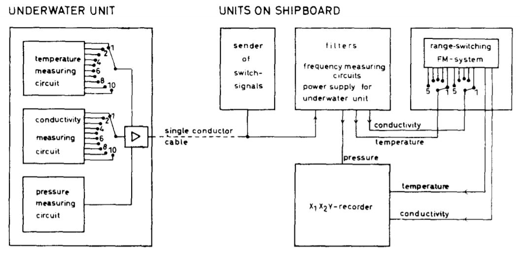
In order to obtain a direct record of temperature and electrical conductivity as a function of depth, the device in addition to the temperature and conductivity probes has a Bourdon tube to measure the hydrostatic pressure. The three measuring probes for temperature, conductivity and pressure are frequency-determining parts of three oscillator circuits which work respectively within the ranges 0.86 to 1.5 kHz; 2.57 to 4.5 kHz and 6 to 9 kHz. To avoid the use of multiconductor cables, as their weight requires a big winch for work at great depths, an especially developed single conductor cable was used to carry the underwater unit with the current returning to the ship through the seawater.

The frequency signals are transmitted back to the ship over the single conductor cable and are either recorded on a magnetic tape recorder or transformed into d.c.-current. Thus, the dependence of the temperature and conductivity on the pressure, i.e., on the depth, can then be recorded on a double-function X-Y-recorder. In order to use the instrument in any oceanic area the following ranges and accuracies were required :
temperature: – 2 to ÷ 35°C; ± 0.02°C
electrical conductivity: 20 to 70 mS/cm; ± 0.02 mS/cm
If all frequency-determining components of the oscillators which are temperature sensitive are installed in a thermostat, the frequency error of the oscillators is less than 1 percent of the frequency range. To achieve such accuracies, the range had to be subdivided. This subdivision can be made (1), in the oscillators and (2), before or (3), after the frequency measurement in the shipboard portion of the instrument. The first provides the greatest and the third the least increase in accuracy. Frequency signals are used to make the switch in the oscillators by remote control when lowering the underwater unit. As this requires some technical care only as many steps for subdividing the range are made in the underwater device as are really necessary; others can be made on shipboard before the frequency measurement. The Kieler Howaldtswerke constructed an instrument according to specifications provided by the IfM.


 Visit Today : 418
 Visit Yesterday : 253
 This Month : 4334
 Total Visit : 358997
 Hits Today : 480
 Total Hits : 792754
 Who's Online : 7