
Resolving space and time
The rapid evolution of the digital computer prompted N.Brown to rejoin WHOI in 1969 to commence the development of a digital instrument to address the limitations of the STD.

In 1970, Brown again developed an improved device that used a 4-electrode MK IIIB CTD conductivity sensor 4-electrode conducting cell in which the two electrodes were deployed internally, and the two electrodes were deployed externally of a small (4 mm square alumina tube×3 cm long) head. In this” contact-type “conductometric cell, the electrodes and tube are configured in the traditional” four-pole resistance measurement ” method.
Four-pole resistance measurement is advantageous because the resistance of the measuring lead wires does not affect the measurement result. Thus, the sensors are connected based on the four measuring terminals that can be excluded from the calculation of the conductivity of the fluid mixing variables arising both from the lead-in wires and more difficult to stabilize the impedances of the electrodes.

It measured temperature using a combination of a very stable platinum thermometer with a typical response time of 250 milliseconds and a thermistor with a response time of approximately of 30 milliseconds. The outputs of these two sensors were combined in an analog circuit that had the stability of the platinum thermometer and the speed of the thermistor with no sensitivity to the steady-state calibration errors in the thermistor. The combined output was digitized along with the pressure and conductivity sensors. Experience showed that due to the variability and complexity of the time response of these sensors, it was better to digitize their outputs separately and combine the outputs numerically on the computer. One key development in the CTD was the high resolution (16-bit) AC digitizer, which had a noise level of 0.1 microvolts at a rate of 100 samples per second. With a thermistor response time of 30ms, the 10cm vertical resolution was possible with profiling speed 0.5m/s and sampling rate 10Hz.

Following the publication of his work in 1974, N.Brown left WHOI to form Neil Brown Instrument Systems, Incorporated (NBIS Inc.) to manufacture the Mark III CTD.
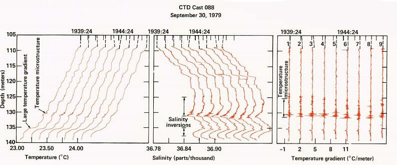
The MK IIIB CTD and sensor were a significant commercial success and were the tool that established CTD as the primary tool for collecting high-resolution oceanographic salinity data. Since the original design goal of the MK IIIB was to provide a very high vertical resolution of salinity profiles, the small size of the MK IIIB conductivity sensor, combined with its partial external field, were acceptable technical compromises compared to the desire to achieve absolute measurement stability. It has become a common scientific practice to adjust CTD data based on reference salinometry made on discrete water samples that were collected at the same time. The small length of the MK IIIB sensor provided the sensor with a short flushing interval so that it responded quickly to changes in conductivity. It was known as the “microstructure ” sensor.

The range in temperature is about 32 °C, from freezing to nearly the warmest surface water. For packing efficiency, straight binary integers were used. Thus a 16-bit (65536) measurement of temperature gives 0.5 millidegree resolution and 0–32.8 °C range. (For some work, a -2 °C lower end is needed and this was later incorporated.) Conductivity varies over the same range because it tracks temperature. Sixteen bits generally permit practical salinities up to 38 to be measured to 0.001 precision.

The depth range needed for most of the ocean is 6500m (or a pressure range of 6550 dbar) and, with a digitizer capable of 16-bit resolution, 10-cm depth resolution is permitted, again right on target for the resolution of the sensors. But to make a measurement to a 16-bit and have it remain accurate and stable is not easy. Furthermore, the conductivity measurement must be made at about 10 kHz to minimize electrode polarization. Neil Brown’s solution to these problems was to make all of the digitizations with transformer windings, weighted in a binary sequence, and added electronically. These were driven at 10 kHz so that polarization effects were minimal. Precision in the measurements was ensured by the turns ratio in the transformer.
Practical solutions to the requirements of very high accuracy and reasonable speed are hallmarks of the very best instruments and the Mark III CTD established a standard.

Since the early 1970s when the Mark III CTD was developed, microprocessor technology has undergone spectacular evolution. At the same time, the demand for CTDs with custom modifications and additional sensors became the rule rather than the exception. As a result, the Mark V CTD was developed starting in 1987 (at that time NBIS was acquired by EG&G) to take advantage of microprocessor technology so that most custom modifications and calibration adjustments could be made in software rather than in hardware, thus simplifying the manufacturing process. Another important difference is the use of a six-electrode conductivity cell that promises substantially improved stability. It is sensitive to the external seawater at one end of the cell and not sensitive to seawater inside the cell. All six electrodes are inside the cell, remote from its sensitive area. However, the electronics necessary for this cell are inherently complex. The Mark V CTD uses a titanium pressure sensor that is about three times more accurate than the sensor used in the Mark III system.
In 1989 Neil Brown left EG&G and returned to the WHOI.


 Visit Today : 369
 Visit Yesterday : 253
 This Month : 4285
 Total Visit : 358948
 Hits Today : 420
 Total Hits : 792694
 Who's Online : 6